3U Eurorack module,
14HP wide,
20mm deep
Weight 0.5 kg
current draw: 50mA
How to use Cwejman Ribbon cable connectors
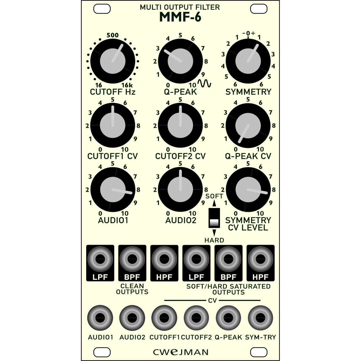
User manual MMF-6
The MMF-6 is a multi mode filter with six outputs, first three from the left; “clean” low pass, band pass and high pass. Low- band- and high pass to the right are processed by three separate (for every output) saturation circuits with two modes; soft and hard. Additionally, the filter core has so called “symmetry” control for the resonance and cutoff frequency. It is possible to control cutoff so positive and negative going signals has different cutoff frequencies, from a subtle “edge” to very dramatical character of the audio signal (including frequency division effect). All this by modulating symmetry by one of outputs (pre-patched to “clean” low pass output) or an external signal. Now it is possible to mix clean and saturated audio signals in any combination.
Inputs:
Audio: 2x In
CV inputs: 2x cutoff, 1x Q-peak, 1x symmetry
Outputs:
clean LPF, BPF and HPF
saturated LPF, BPF and HPF
dimensions
The SPH-1 is a 14-stage stereo image phaser. It consist of two identical voltage controlled all-pass filters with seven notches stretched over the whole audio range which ensures constant phasing effect.
The all pass filters are combined with original audio signals resulting in an almost constant gain and phase shift of 2400 degrees across the entire audio range (see diagrams below).
Additionally, the phasing effect remain almost constant even in saturation mode.
Phasing (SPECTRUM) is controlled by modulating low frequency oscillator (MOD RATE, MOD LEVEL) and by external signals (SPECTRUM CV, and separate SPECTRUM LEFT, RIGHT).
The low frequency oscillator’s rate can be modulated by external signal (RATE CV, RATE CV INPUT).
The SPH-2 provides one audio input for both phasers labelled by SUM AUDIO.
The audio outputs are provided by output socket labelled AUDIO, LEFT, MIX (mixed left and right phaser) and RIGHT. Outputs are revealed by white surrounds.
The FEEDBACK knob controls the amount of multi resonance for both phasers up to self-oscillating.
The SPATIAL/ROTATING switch couples phaser between two different stereo images. The BYPASS/ L&R INPUT inserts both phasers in the audio chain in position L&R INPUT.
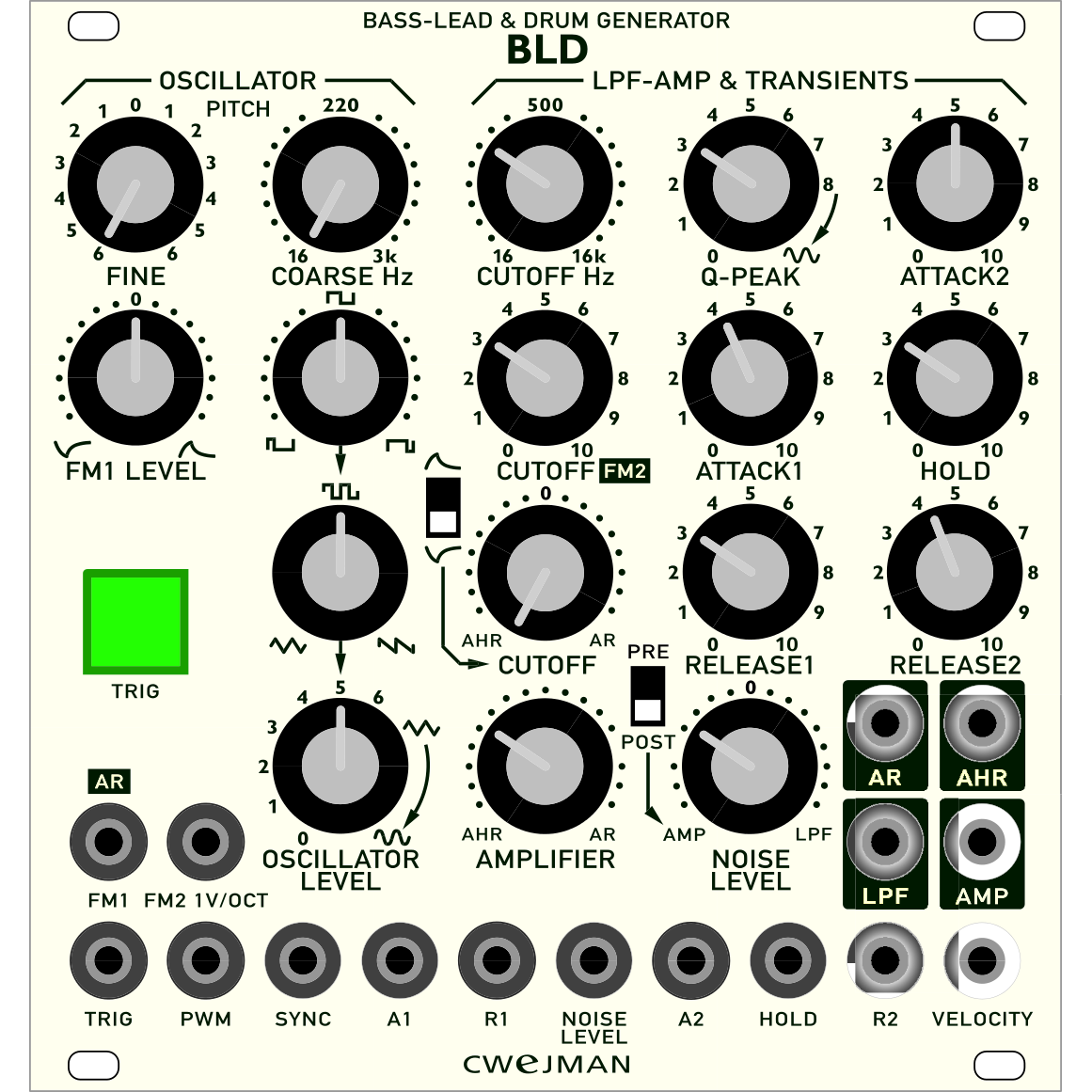
The BLD has all components and function necessary for generating bass lead and drum sounds with focus on bass drum sounds.
The BLD contain main sound generator (OSCILLATOR) and noise generator and modifiers such as low pass filter, amplifier and two transient (contour) generators.
Oscillator has two manual pitch controllers (FINE, COARSE) and two inputs for controlling the pitch by external signals (FM1, levelled, bipolar pre-patched to transient generator AR and FM2, calibrated to 1 Volt/octave).
Waveforms and mix between shapes is controlled manually from triangle, mix between triangle and pulse, pulse, mix between pulse and saw tooth and saw tooth).
Oscillator level is controlled manually from 0 thru nominal signal strength to saturated (curved, for more punch). Pulse width is controlled manually and by an external signa (PWM).
NOISE GENERATOR is connected to the low pass filter and to the amplifier (NOISE LEVEL). The noise generator can be routed in to the amplifier (PRE) or directly to the output AMP (POST).
The noise generators level is also controlled by pre-patched AR generator thru input NOISE LEVEL.
AR and AHR transient generators are activated manually by the push button
TRIG and/or by an external signal (input TRIG). Attack, Hold and Release are manually controlled and by an external signals connected to inputs A1, R1 (AR) and A1, HOLD and R2 (AHR).
AMPLIFIERs gain is controlled by mix of AR and AHR and by an external signaln connected to the input VELOCITY

 MMF-6 マルチモードフィルター